
A Button and an LED
Programming is in my comfort zone. Fiddling with wires, LEDs, resistors, and buttons is not. (I spent my whole life until now calling it a resister). I was both excited and nervous to start.
That said, there are so many fantastic YouTube videos out there covering exactly this topic, adding a button and/or an LED to a Pi project, that this was surprisingly easy to accomplish. What was challenging is that I wanted to accomplish more than assembling a lego kit, I wanted to understand why we are doing it this way.
For example, when creating a circuit for the LED it seems straight forward:
Power -> LED -> Ground.
Everyone said I needed a resistor. OK:
Power -> LED -> Resistor -> Ground.But there was wild inconsistency on what type of resistor to use, and seldom an explanation of why.
And for that matter, what is a resistor? What's an Ohm(Ω)? I get that 3.3V is Volts.. but I have no idea what a Volt really is and how it relates to resistance or current?
To figure this stuff out, I'm going to implement this in three steps. The code files are located in powerzero/learning/button_and_led.
- Make an LED Blink.
- Make a Button Detect a press.
- Add them together and make the button change how the LED blinks.
1. LED Blink
powerzero/learning/button_and_led/led_blink.py
There are so many better and more detailed tutorials online and on YouTube that I'll just share what I did so that we have some consistency with the sample code.
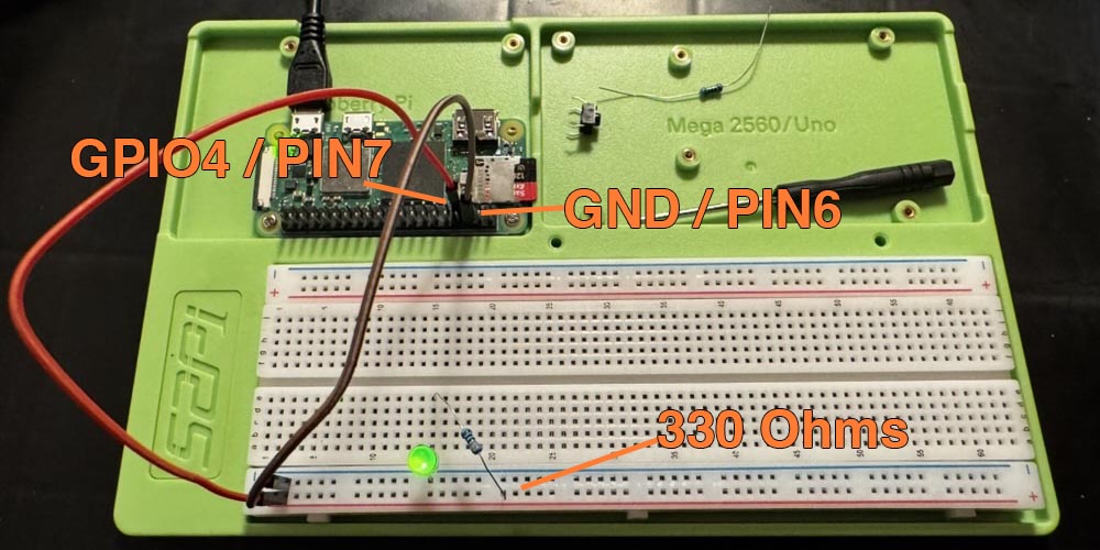
- Plug a wire from GPIO 4 / Pin #7 into the red (+) column on the breadboard. These columns are connected all the way up/down the board.
- Plug a wire from GND / Pin #6 into the blue (-) column on the breadboard.
- Plug an LED into the board, one side into the (-) column, one side into a row next to it. For discussion sake, I used row 15. LED direction matters. The LED should have two wires, one longer than the other. The long wire is (+) and the shorter wire is (-). The shorter (-) wire should plug into the (-) column. And the longer (+) wire into the row on the other side of the blue line.
- Plug the 330Ω resistor so that it bridges the (+) side of the LED (row 15) to the (+) column on the edge of the breadboard.
- 330Ω is orange, orange, black, brown, gold. According to ChatGPT, A 330Ω resistor is ideal for this setup, but resistor values in the 200–500Ω range will also work. Lower values risk overheating the LED, while higher values may cause dimming. There are helpful resouces online to help you decode a resistor. I'm sure it eventually becomes natural, but I really struggled. I eventually started to use ChatGPT to help.
To execute the code, there is more detail in Remote Coding, but in short:
- In one terminal window, ensure
tools/sync.py -s initialize -c learnis running - In another terminal window, SSH into the Pi
- On the Pi, cd to
/projects/powerzero/learning/button_and_led/to see and execute the sample code files.
tools/bootstrap.py -s initialize -c learn) before you run sync if you haven't already done so.
Future Me Discovery:
GPIO4 worked fine when the Raspberry Pi was mostly bare, but as I added more components (I2C, SPI, I2S, etc.), it somehow got reassigned to sdmode, and the test code would output lgpio.error: 'GPIO Busy'. I think sdmode is related to SD card detection or power management, but I haven’t fully tracked down what triggered it.
Workaround: Rather than fighting it, the simplest fix is to pick another GPIO pin (e.g., GPIO17, GPIO27, or GPIO22) and update both the wiring and code accordingly.
2. Button Detect
powerzero/learning/button_and_led/button_detect.py
The plan is to connect a button and print something out in the terminal when you press it. This time it occured to me that the colour of the wires might be relevant from an organization standpoint as the circuits begin to get more complex. It also occurred to me that I should think about the the assembly of the circuit in a path with the flow of the current.
I don't know which direction is correct, but I decided on (+) to (-) or power to ground as this seemed most intuitive. I'm going to outline the circuits in this manner going forward. The circuit for the button is below:
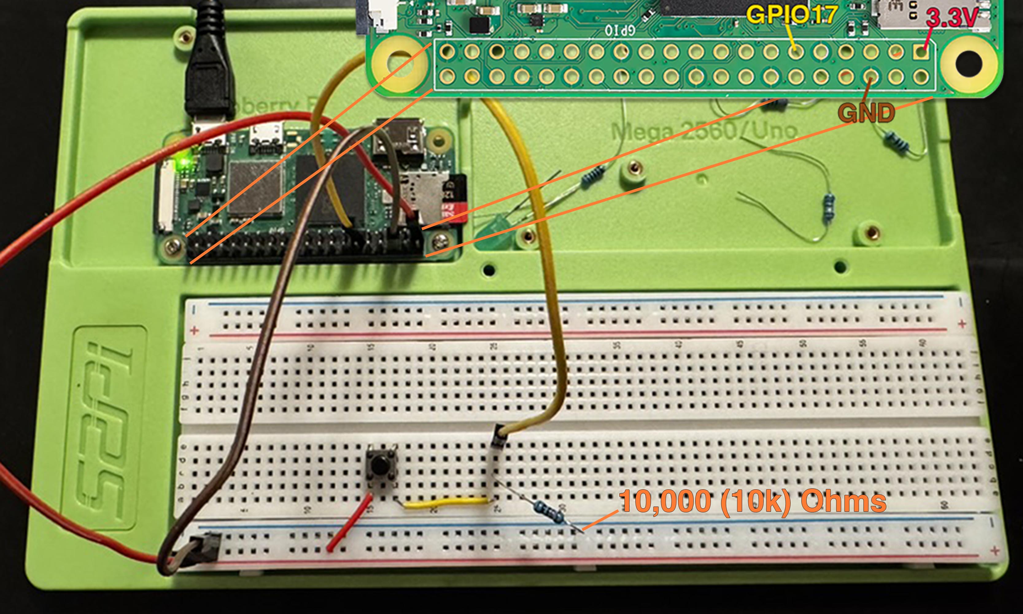
- RED: Connect 3.3V power from Pin 1 on the Pi to the positive column (+) on the board
- RED: Connect the column (+) to a row where we'll put the button — Let's say 15.
- BUTTON: Connect it so that legs 1 and 2 are on row 15, and legs 3 and 4 will be on a different row depending on the size of your button. For me it's row 17.
- YELLOW: Connect row 17 to something slightly down the board just to give yourself more room to work. I used row 25.
- YELLOW: Place a yellow cable from row 25 to GPIO17, which is Pin 11 on the Pi
- RESISTOR: Place a 10,000Ω (10kΩ) resistor from row 25 to the negative (-) column
- Color code: brown, black, black, orange, gold
Button Configuration
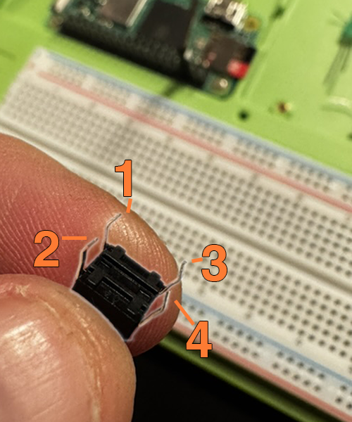
The button I'm using has four pins. Because I'm thinking of it in orientation to the breadboard, pins 1 & 3 are on the left side of the button and towards the first row of the board (in my case plugged into row 15), and pins 2 & 4 are on the right (plugged into row 17).
- Pins 1 & 3 are internally connected.
- Pins 2 & 4 are internally connected.
- When you press the button, it connects all the pins.
Circuits and Resistors
I really struggled to figure out what is going on in this circuit. Notice that in the diagram above, button pins 3 & 4 connect via yellow wire to GPIO17 and to the negative column via the 10,000Ω resistor. (I know the standard is to say 10kΩ. My thumb has a melty resistor imprint to remind me to read more carefully; but I want to save you that pain. Early on I misunderstood this critical detail and used a 10Ω resistor that effectively created a short circuit when combined with an incorrect button orientation and got super hot.)
So it appears to me that the 3.3V red wire is going into one side of the button, and the othe side is connecting to both ground and GPIO17. So why what's going on here?
From what I can figure out, the GPIO is expecting a digital input. So 0V when the input is off, and 3.3V when the input is on. And GPIO17 is looking for and reporting these two states. The python code can detect the state of the pin based on these expectations:
When the button is not pressed, the circuit is open, meaning the path from 3.3V to GPIO17 is incomplete, so no current flows from the 3.3V source to GPIO17. But what about GPIO17? How does it detect 0V? That’s where the resistor to ground comes in. The resistor provides a path to ground, allowing GPIO17 to detect 0V when the button is not pressed.
When the button is pressed, the circuit is closed across the button, so current flows into GPIO17. Since that current is connected to the 3.3V Pin 1, GPIO17 sees the 3.3V and reads that as the on state.
Working through this, I have learned that this is a pull-down resistor.
Future Me Discovery:
The Raspberry Pi has a built-in mechanism that eliminates the need for an external pull-down resistor. Instead, you can configure the GPIO pin to use its internal pull-up resistor. This means we don't need our resistor, and we simply tell the Pi that we're going to use the internal pull-up resistor instead:
With an external pull-down resistor, the GPIO pin stays at 0V (LOW) until the button is pressed, at which point it connects to 3.3V (HIGH). To use the internal pull-up resistor, we connect to GND instead of 3.3V. So when the button is pressed the GND connection is made. Beyond setting pull_up=True, no other code changes are required.
3. Button and LED
powerzero/learning/button_and_led/button_led.py
Now that we've achieved both components operating independently, we'll put them together into a single circuit. The demo code will play different 'patterns' of blinks with the LED, and pressing the button will advance to the next pattern.
This circuit is an add-on to the existing circuit from the button detect above. Once you have that in place:
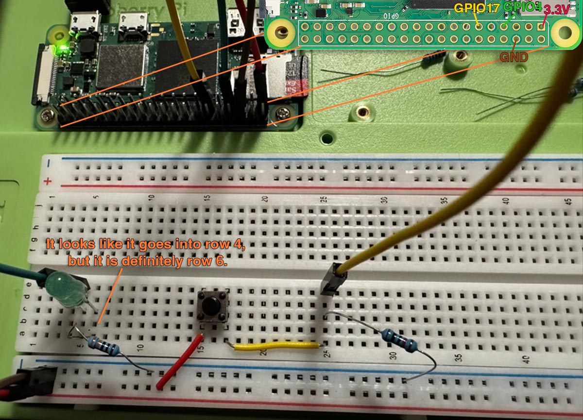
- GREEN: Plug GPIO4 / Pin 7 into row 5 of the breadboard. The GPIO will act as a controllable power source, switching between HIGH (3.3V) and LOW (0V) to turn the LED on and off. I chose green for no better reason than because the LED is green.
- LED: Plug the long leg of the LED (+) into row 5 where we just plugged the GPIO wire, and the short leg (-) into row 6.
- RESISTOR: Place a 330Ω from row 6 into the vertical (-) on the board that is already connected to GND.
- 330Ω is orange, orange, black, brown, gold.
Next Steps
Now that I have some concept of adding wires to components and creating circuits, I thought I would add the real-time clock (RTC) module as it's probably the most critical components in the build.
Next Up: Time Unplugged