
Hello Sound
The goal is simple: play voice recordings that describe power events. Eventually, I’ll use Text-To-Speech (TTS) to generate messages like, "A severe power outage was detected on January 10th, lasting four hours."
For now I just want to be able to play an MP3 file. I didn't realize that this decision alone would trigger a bunch of confusing steps. And as I've stated earlier, the selection of the PAM8302A was also an error. In my defense, that was two weeks ago and I hadn't even installed Raspberry Pi OS, which is another way of saying I didn't know nuthin.
The PAM8302A is an analog amplifier, great for generating tones from simple frequencies. The MAX98357A, on the other hand, is a digital amplifier — it can play full audio files like WAV or MP3.
Because of delays associated with this part of the project, I completed Pixels on the Pi before I got the MAX98357A boards delivered. And this sort of fits what I'm discovering about the Pi and these external boards — you connect the wires right, maybe adjust something in config.txt, and it just works. Wow.
To execute the code samples, there is more detail in Remote Coding, but in short:
- In one terminal window, ensure
tools/sync.py -s initialize -c learnis running - In another terminal window, SSH into the Pi
- On the Pi, cd to
/projects/powerzero/learning/hello_sound/to see and execute the sample code files.
tools/bootstrap.py -s initialize -c learn) before you run sync if you haven't already done so.
Wiring the PAM8302A
My first attempt was with the PAM8302A. At this point, I was feeling confident — perhaps too confident. I wired it up, ran the test code, and… well, I didn't know what I didn't know.
Connections
- BLACK: Connect GND from the amplifier to Pin 6 (GND) on the Raspberry Pi.
- RED: Connect 5V from the amplifier to Pin 2 (5V) on the Raspberry Pi.
- YELLOW: Connect SD (shutdown) to Pin 11 (GPIO17) on the Raspberry Pi.
This is optional. You can also leave it unconnected, or tie to 3.3V for always-on. - GREEN: Connect A+ (Audio In+) from the amplifier to Pin 12 (GPIO18, PWM Audio Signal).
- BLUE: Connect A- (Audio In-) from the amplifier to Pin 6 (GND) on the Raspberry Pi (bridged with BLACK wire).
Connecting it was easy, and everything worked as expected — at least in terms of playing waveforms. The code snippet below will play a sort of startup sound of three notes. I'll skip the rest of the drama, but it took me far to long to realize that this board is not designed to play back digital audio files.
Wiring the MAX98357A
After about ten hours trying to play audio files on the PAM board — then waiting a week for the MAX to arrive — I had no patience for loose wires. I bought a soldering station and got to work. (SEEKONE 60W Soldering Station) I used this to attach the pins that came with the package to the MAX board. Then I could just stick the MAX directly into the breadboard. (And thus trade my concerns that loose wires were causing audible pops in the sound with concerns that my shoddy soldering was).
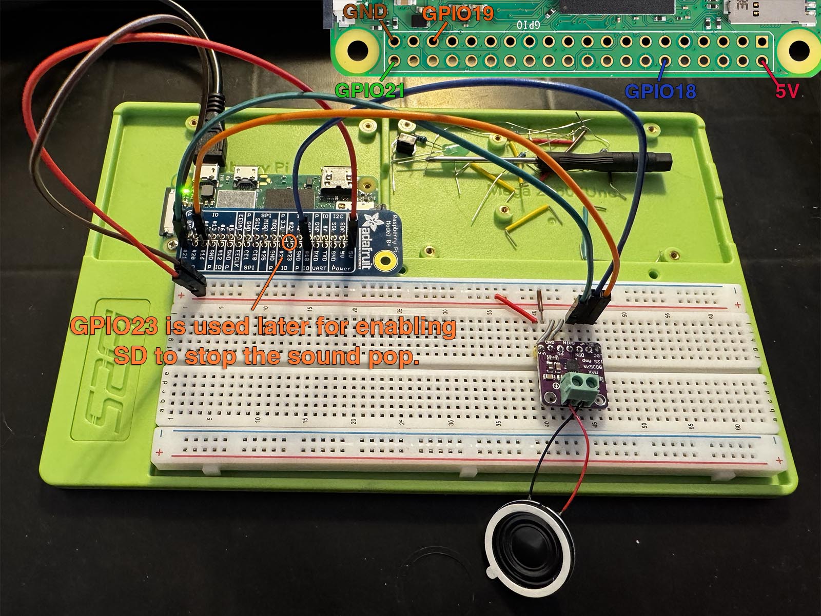
I then stuck it into the board spanning from rows 40 through row 46. The pins on the MAX are labeled (from rows 40 → 46) as VIN (40), GND, SD, GAIN, DIN, BCLK, and LRC (46).
- RED: Plug a wire from 5V / Pin #2 on the Pi to VIN on the amplifier (row 40).
- BLACK: Plug a wire from GND / Pin #6 on the Pi to GND on the amplifier (row 41).
- Bridge breadboard VIN (row 40) → SD (row 42).
- Bridge breadboard GND (row 41) → GAIN (row 43).
- GREEN: Plug a wire from GPIO 21 / Pin #40 on the Pi to DIN (row 44).
- BLUE: Plug a wire from GPIO 18 / Pin #12 on the Pi to BCLK (row 45).
- ORANGE: Plug a wire from GPIO 19 / Pin #35 on the Pi to LRC (row 46).
Adding the Speaker
The MAX98357A provides mono output, so we connect one speaker:
- RED: Connect the positive (+) speaker wire to the speaker + terminal on the PAM board.
- BLACK: Connect the negative (-) speaker wire to the speaker - terminal on the PAM board.
Configuring Bootstrap
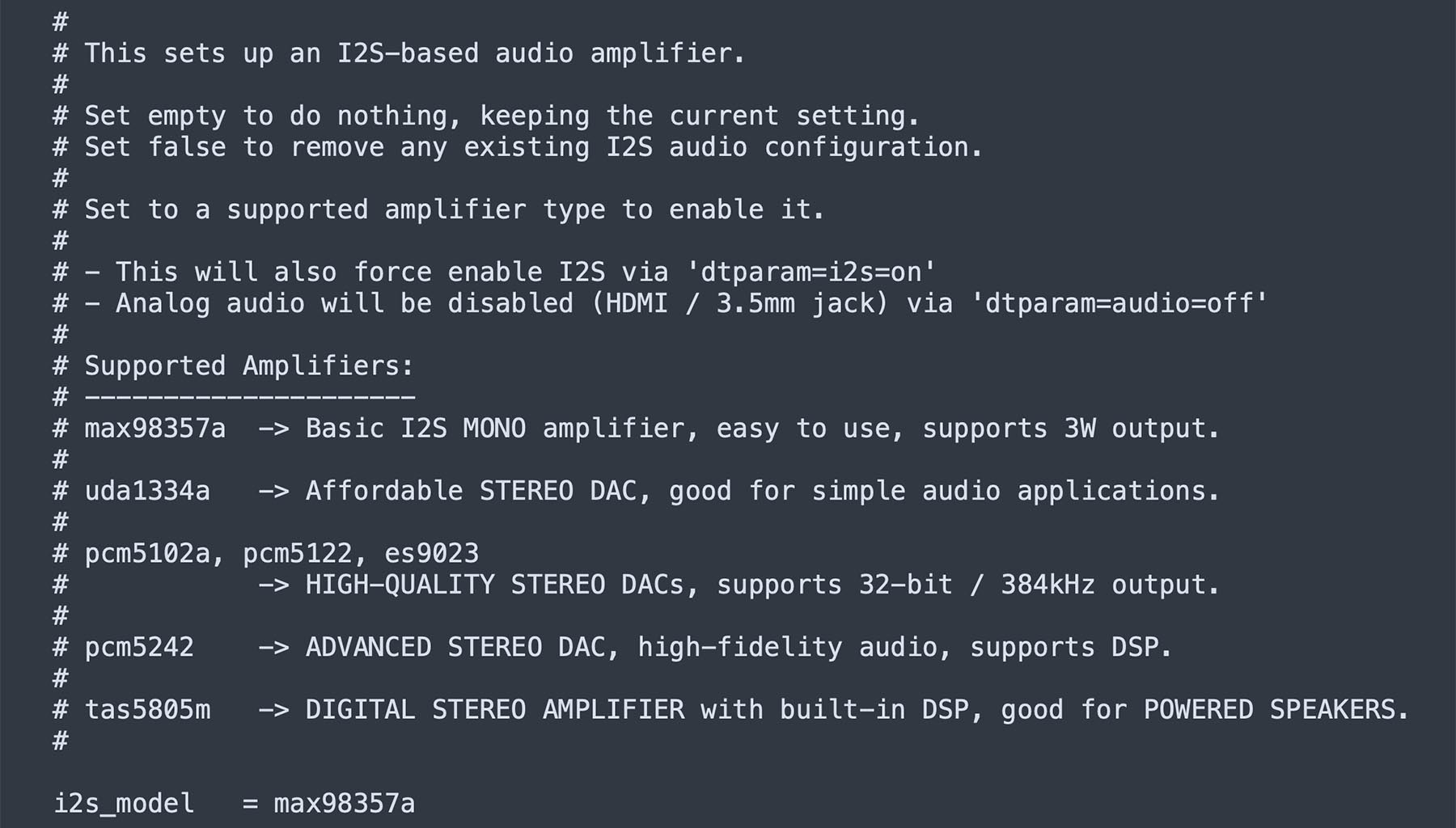
To avoid being repetitive, reference the Remote Coding on how to deploy the configuration to the Pi.
Playing More than Beeps and Boops
Want to check if your speaker even works? Start with speaker-test. SSH into the Pi and run this command:
speaker-test -D hw:0,0 -c 2 -t sine -f 1000
Now assuming that's working, you should hear a tone alternating between the left and right speaker. Since we only have one speaker on the MAX, you'll only hear the tone when it plays in the left. You can also play something using aplay:
aplay -D plughw:0,0 /usr/share/sounds/alsa/Front_Center.wav
If everything is wired correctly, you should hear "Front Center" through the speaker.
If you read ahead and decided to pre-emptively connect the SD to a GPIO pin, no sound will come out with the aplay command. speaker-test will work, but aplay will just click as the board powers up and then nothing. Ensure SD / breadboard row 42 is connected to 5V power for aplay to work. I had a few hours of fun figuring out why this command suddenly stopped working, but my code did.
Pop Pop Pop
Whenever you play a sound, you'll probably hear a loud popping sound. To get rid of this, we need to do two things:
- YELLOW: Plug a wire from the SD (row 42) to GPIO 23 (Pin 16) on the Pi. Of course, you need to remove the jumper connecting rows 40 → 42.
- Turn the amplifier on and stabilize it before playing a sound.
2V-5.5V? I don't think so.
From what I read the PAM has a wide operating range from ~2-5V. I decided to use the 3.3V for no particular reason, but why not? It's in the middle of the range. I couldn't get quality sound without plugging it into the 5V. When I did, suddenly the audio became super clear and the static went away.
Future Me Discovery:
I sort of ignored the GAIN because it didn’t seem I needed it. I just grounded it. Turns out, grounding GAIN sets the amplifier gain to +3 dB, while leaving it floating increases it to +15 dB. I had inconsistent results, so I decided to keep it bridged.
Also, what is a decibel? There doesn’t seem to be a volume control per se, like there’s no knob that goes from 1 → 11. Instead, you modify it by some number of dB, which changes the gain, which in turn affects how much power (watts) goes to the speaker. But here’s the trick: it’s a logarithmic scale, not linear.
If by default you have 1 watt going to the speaker:
- +3 dB → Doubles the power (1W → 2W)
- +10 dB → 10× the power (1W → 10W)
- +20 dB → 100× the power (1W → 100W)
But here’s where it gets weird: power is not the same as how loud it sounds. We don’t hear in a linear way either:
- +10 dB sounds about twice as loud (not 10× louder).
- -6 dB cuts power in half, but it won’t sound half as loud — just a bit quieter.
Next Steps
Sound? Working. Now, time to make the Pi show something too.
Next up: Pixels on the Pi.