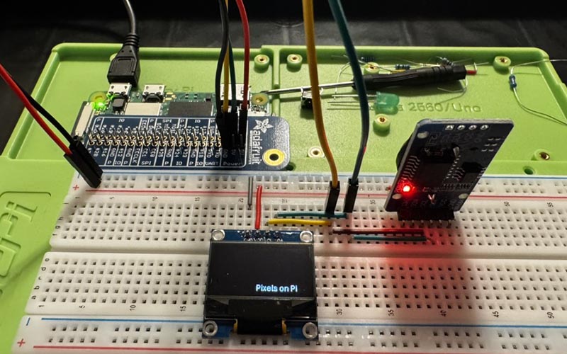
Pixels on the Pi
Surprisingly, this stretch goal was the easiest part of the project so far. I'm sure some of this might be related to having gained at least some level of experience, but ultimately it was truly plug-and-play.
While I ordered a few different screens, I quickly narrowed my focus to the two that I thought would be the best options:
| Module | Resolution | Price |
|---|---|---|
| SH1106 1.3" OLED Black/White SPI Connection |
128 x 64 pixels 29.42mm x 14.7mm |
$8 - $15 |
| SSD1306 0.96" OLED Black/White I2C Connection |
128 x 64 pixels 21.74mm x 11.18mm |
$5 - $8 |
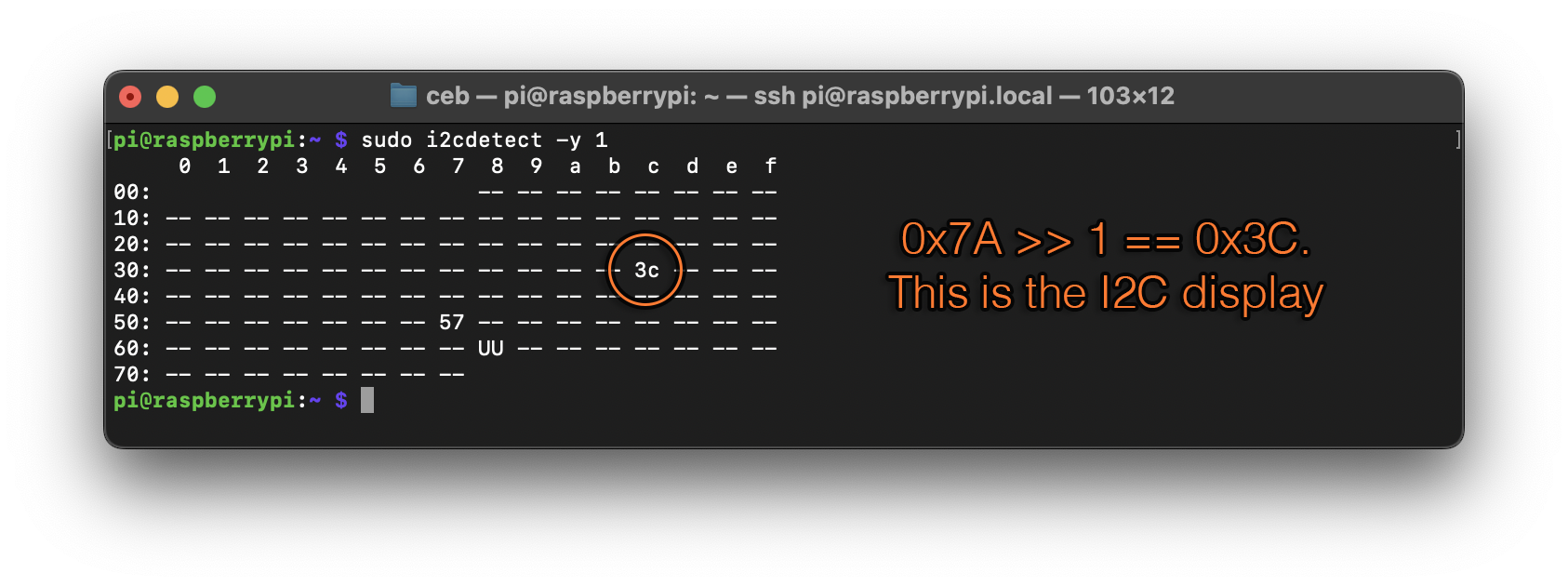
I2C (inter-integrated circuit) is a synchronous serial communication standard. It allows you to connect multiple items on the serial bus. It has four pins (GND, VCC, SCL (clock), SDA (data)), and the same two communication pins (SCL, SDA) can be used to talk many devices all connected at the same time. When you send messages over I2C, you also include an address for the device. The oled screens, for example, are at address 0x78 or 0x7A. I2C is slow but versatile.
SPI (serial peripheral interface) is also a synchronous serial communication standard. The screens have seven pins, four of which map to the SPI standard (SDA → MOSI, SCK → SCLK, CS → CS, and MISO is unused for these screens). It uses three (or four) pins to communicate, making it about 25 times faster than I2C. It can have multiple devices on the SPI bus, but each device needs a unique CS pin. All devices share the common communication lines, but only the device with its CS pin pulled low (0V) will respond to commands. Because of this dedicated selection pin, SPI does not require passing an address like I2C does. SPI is fast but requires more effort for multiple devices.
Future Me Discovery:
I2C device addresses are 7-bit, ranging from 0x00 to 0x7F. However, some datasheets represent this 7-bit address shifted left by one bit (address << 1), placing it in the most significant bits of a byte.
This is why these display modules might list addresses like 0x78 or 0x7A.
In reality, the Raspberry Pi expects the 7-bit address, so you need to shift it back down (address >> 1) to get the correct value.
TL;DR: If your datasheet says 0x78, use 0x3C in your code. If it says 0x7A use 0x3D.
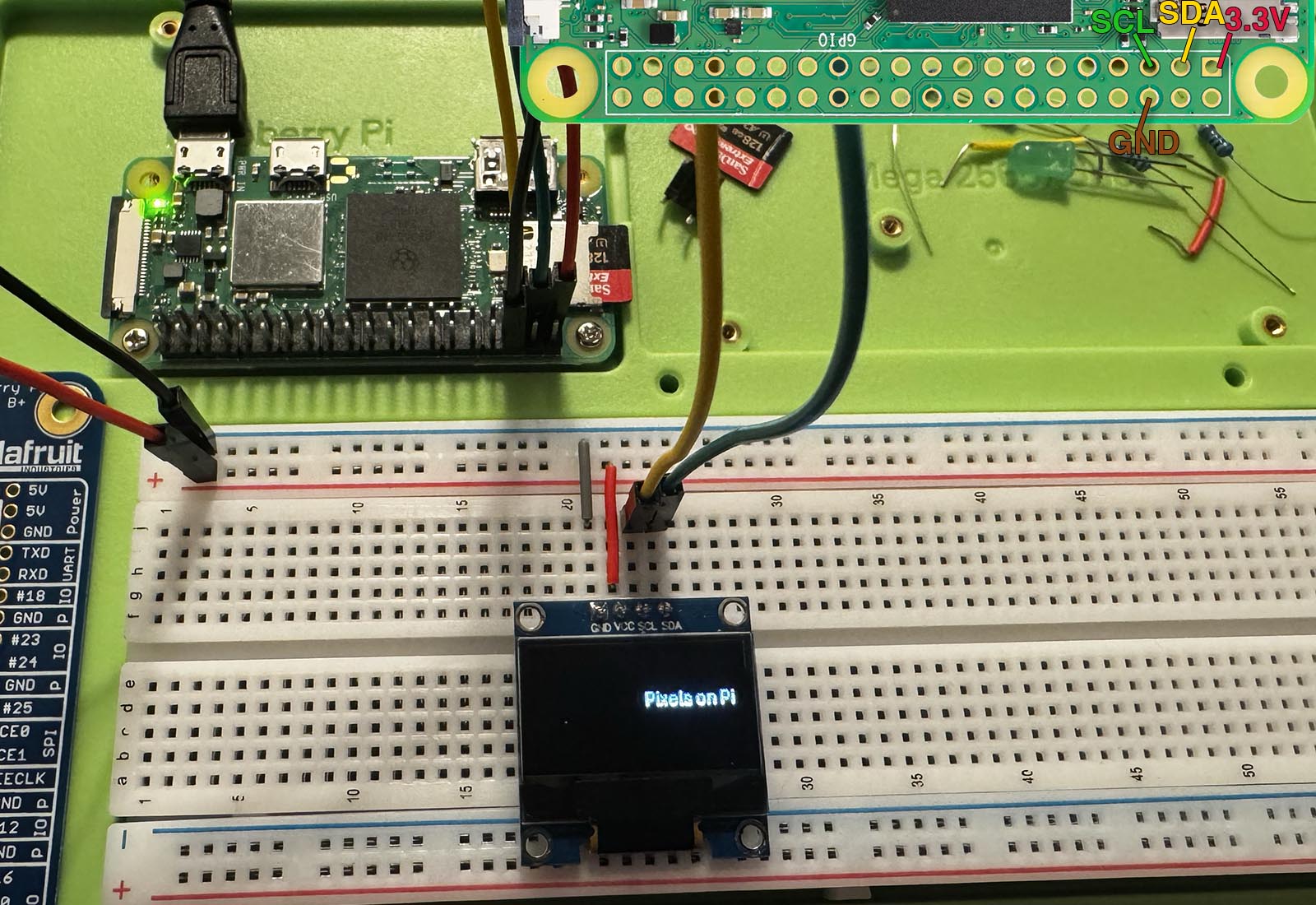
SSD1306 0.96" I2C OLED Wiring Guide
The OLED module has soldered pins which are inserted directly into the breadboard, spanning from rows 20 through 23. Power connections are routed through the breadboard’s +/− power rails, with small jumper wires connecting to the appropriate rows.
The pins on the OLED display are labeled (from rows 20 → 23) as GND (20), VCC (21), SCL (22), and SDA (23). Check the pins carefully as some suppliers swap VCC/GND on the first two pins. Wiring instructions are ordered from top of the board to the bottom (row 20 to 23):
- BLACK: Connect GND (row 20) to the breadboard’s GND rail, which is then connected to Pin 6 (GND) on the Raspberry Pi.
- RED: Connect VCC (row 21) to the breadboard’s 3.3V rail, which is then connected to Pin 1 (3.3V) on the Raspberry Pi.
- YELLOW: Plug a wire from GPIO 3 (SCL) / Pin 5 into row 22 (SCL pin of the OLED).
- GREEN: Plug a wire from GPIO 2 (SDA) / Pin 3 into row 23 (SDA pin of the OLED).
To execute the sample code, there is more detail in Remote Coding, but in short:
- In one terminal window, ensure
tools/sync.py -s initialize -c learnis running - In another terminal window, SSH into the Pi
- On the Pi, cd to
/projects/powerzero/learning/pixels_on_pi/to see and execute the sample code files. - Ensure you setup the virtual environment, and then you can execute the file
i2c_oled.py.
tools/bootstrap.py -s initialize -c learn) before you run sync if you haven't already done so.
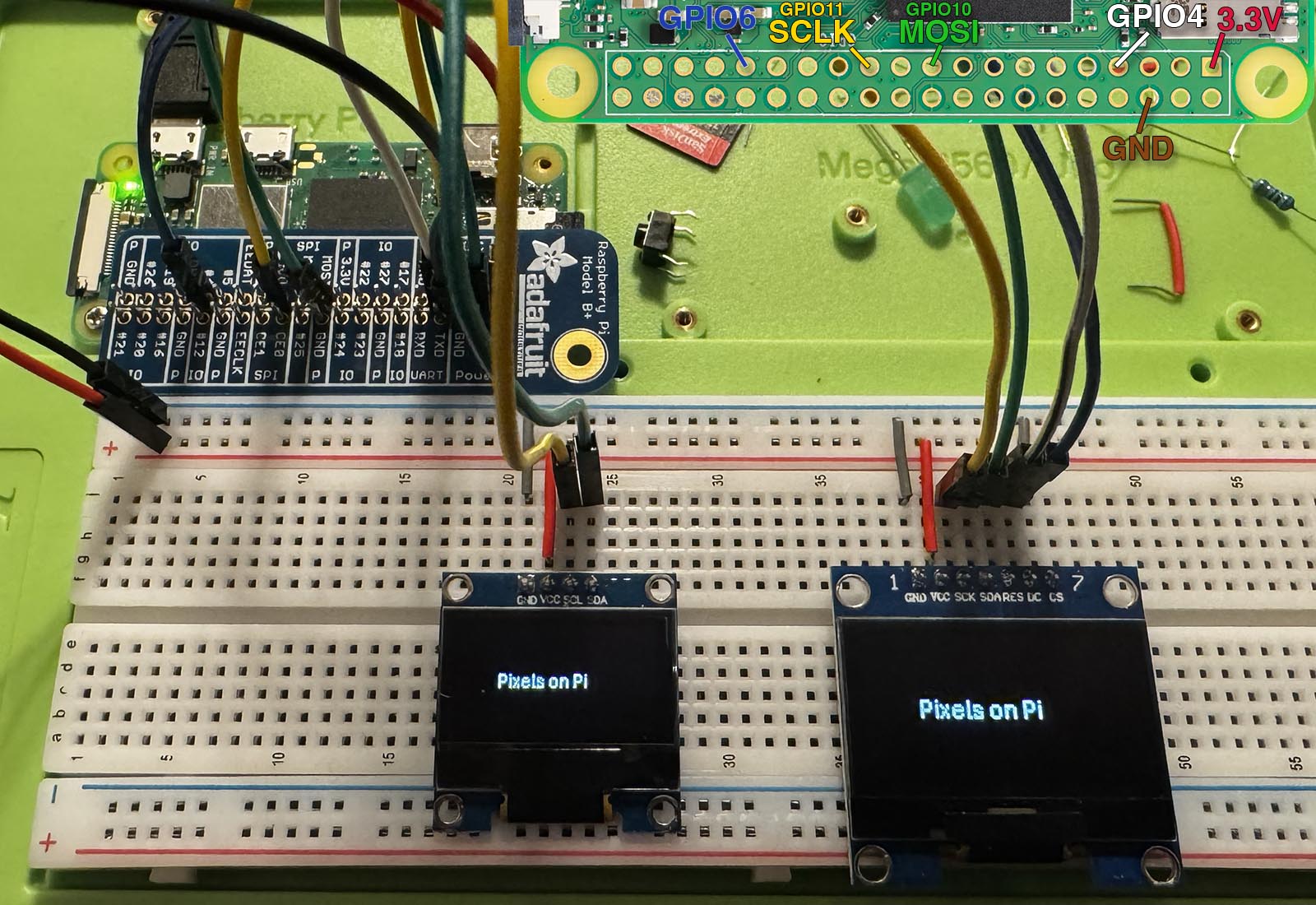
SH1106 1.3" SPI OLED Wiring Guide
I added the second screen onto the same breadboard as the first one. There is a test code sample just for the 1.3" SPI display (learning/pixels_on_pi/spi_oled.py) as well as test code to run both screens at once (learning/pixels_on_pi/double_oled.py).
The OLED module has soldered pins which are inserted directly into the breadboard, spanning from rows 40 through 46. Power connections are routed through the breadboard’s +/− power rails, with small jumper wires connecting to the appropriate rows.
The pins on the OLED display are labeled (from rows 40 → 46) as GND (40), VCC (41), SCK (42), SDA (43), RES (44), DC (45), and CS (46). Wiring instructions are ordered from top to bottom:
- BLACK: Connect GND (row 40) to the breadboard’s (-) GND rail.
- RED: Connect VCC (row 41) to the breadboard’s (+) 3.3V rail.
- YELLOW: Plug a wire from GPIO 11 (SCLK) / Pin 23 into row 42 (SCK pin of the OLED).
- GREEN: Plug a wire from GPIO 10 (MOSI) / Pin 19 into row 43 (SDA/MOSI pin of the OLED).
- WHITE: Plug a wire from GPIO 4 / Pin 7 into row 44 (RES/Reset pin of the OLED).
- BLUE: Plug a wire from GPIO 6 / Pin 31 into row 45 (DC/DataCommand pin of the OLED).
- BLACK: Plug a wire from GND into row 46 (CS/Chip Select pin of the OLED).
Future Me Note:
This wiring differs from common SPI OLED setups, which typically use:
- RES (Reset) → GPIO 25 (Pin 22)
- DC (Data/Command) → GPIO 24 (Pin 18)
If you adjust the GPIO pins to be consistent, you just need to update the initialization on line 4 of the code:
Selecting an OLED Display
I ran some tests on the two displays. From a programming perspective, they behave identically. Other than the obvious one being larger than the other, and the changes for I2C vs. SPI. There is a massive performance difference though. With a simple test of clearing the screen and display a single line of text, the I2C display achieves ~6FPS, and the SPI ~85FPS.
I preferred the smaller form factor as I think it'll fit better into my final vision for the product. And since I already had half a dozen of the smaller displays in I2C format, I decided to go with that. Reasonable people could choose differently.
OLED Display and RTC
Because I decided on the I2C format, I wanted to ensure that there was no conflict with having both the I2C Display and the I2C RTC. To wire them up, instead of wiring SCL, SDA directly to rows 22, 23, I instead wired them to the some rows between the OLED and RTC, and then bridged from those rows to the boards.
I was pleasantly surprised to see that it just worked. No code changes or anything.
Next Steps
I like to minimize variables. For the next step I'm going to wire all the components into a single breadboard and confirm that it all works together in a sort of prototype board that I can first verify all the components with, and second, use to start writing the project code.
Next Up: Prototype Zero