Prototype Zero
Now that I have some level of understanding of the individual components for the build, I wanted to put them together into a single board.
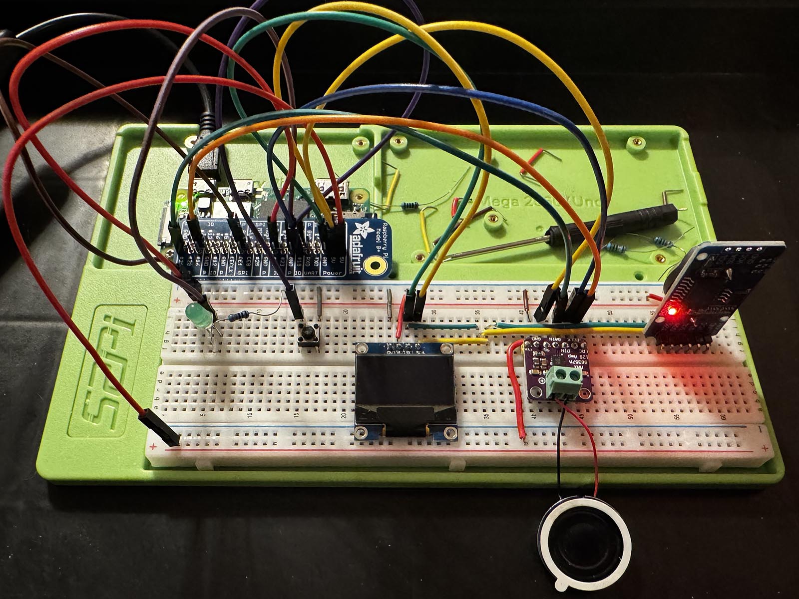
My idea was to continue with the breadboard as the intial prototype so that I can get some test code working to exercise each component simultaneously. This also enables me to refine my decision(s) on the final design requirements.
I basically just followed what I did on each component page and wired it like that. This was pretty easy and only took an hour or so. This strategy enabled me to test everything with the existing code in the powerzero/learning files.
I was pretty pumped that it was all working, but it was fragile and looked so janky.
I Wish I had Wire Strippers
As mentioned in Hello Sound, I had bought a soldering station. I also got a small box of solid core wires and some prototype boards. I chose the MakerSpot Raspberry Pi 3 Prototyping Board which are compact, and I like that the internals are wired similar to a breadboard — this aligned with my plan to translate what I had just built to the prototype.
Before I started, I spent some time thinking through placement of components and how I would run the wires, which resulted in me re-organizing some items and testing those updates on the breadboard.
What I didn't do though was to think through what other tools I might need, or to practice on anything smaller first. I found a pair of wire cutters in the garage which were a poor substitute for wire strippers (using my teeth kinda sucked) — and at one point I had to wait for next-day Amazon delivery of some solder wick and flux paste.
The first board took me most of a day with numerous learning experiences. The only one worth mentioning is test early, test often. I probably worked for about six hours before I plugged the board into the Pi the first time. By this point, I had put so much together I was unable to debug what I had done wrong and nothing worked.
The second board (image below) took less time, took less time, and by testing incrementally, I kept it working the entire way. I learned at least as much completing that board as I did on the first aborted effort. I was tempted to build another one, but I want to move along.
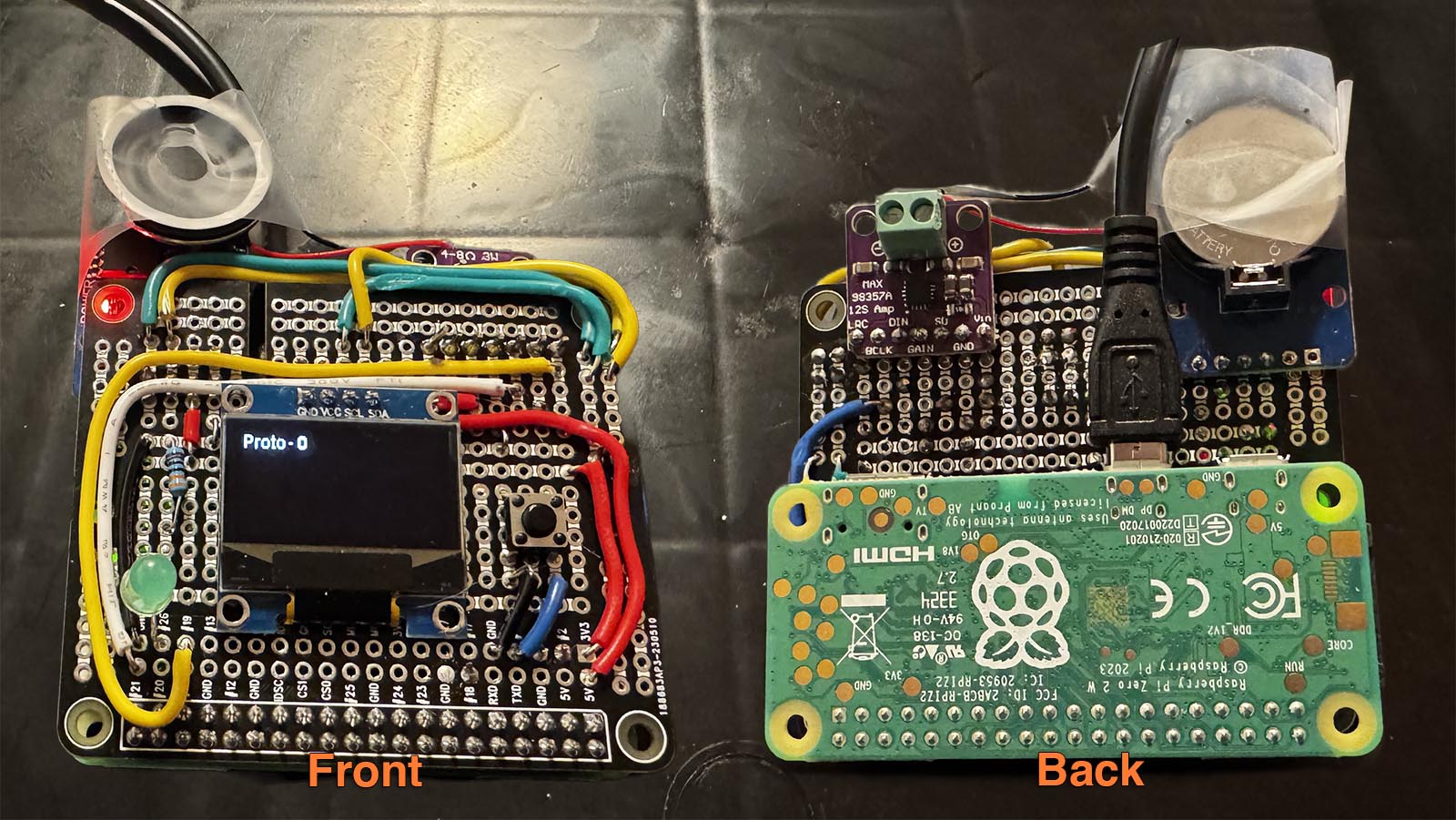 Front and back image of the same board photoshoped together.
I used tape to keep the speaker attached.
Code Sample
There is some sample code that just tests the components. When the program first executes it enables the LED white it converts some sound files and such. The display shows a simple counter. Pressing the button increases the counter, and holding the button resets the counter. There is some sound on button press.
To execute the sample code, there is more detail in Remote Coding, but in short:
- In one terminal window, ensure
tools/sync.py -s initialize -c learnis running - In another terminal window, SSH into the Pi
- On the Pi, cd to
/projects/powerzero/learning/proto/to see and execute the sample code files. - Ensure you setup the virtual environment, and then you can execute the file
main.py.
tools/bootstrap.py -s initialize -c learn) before you run sync if you haven't already done so.
Next Steps
I have a prototype board I can use without fear of wires just falling out. I was originally planning to start the application code, but I've decided to tinker more. First, I want to create a custom PCB to make this easier to reproduce (and I want to learn how to do it).
Next up: Prototype One.
Second, from playing with the UI in this initial prototype, I think a status LED might be a useful signal particlarly when the system is booting. I want to figure out a circuit such that the LED comes on automatically when the Pi gets power, and then somehow use the GPIO to control it once it's fully booted. Due to the turnaround time with the PCB process, I'm going to start this as well — and possibly move on to the project code before the PCB prototype board is finished. We'll see.
Next up as well: LED Part Deux.